Introduction
Cardiovascular diseases have high morbidity, disability, and mortality rates, thus severely affecting human life and social development [1]. Cardiovascular intervention technology is an emerging tool for the diagnosis and treatment of cardiovascular diseases, in which lesions in the body are diagnosed and treated with guidewires or catheters under fluoroscopic guidance [2–4]. However, this image-guided technology requires extensive operator experience, particularly in the field of recanalization of coronary artery chronic total occlusion or stem cells for myocardial repair [5].
Soft continuum microrobots, with their ability to continuously morph into diverse shapes, are increasingly being used in medical applications [4, 6–8]. Notably, soft continuum robot can perform a range of therapeutic and diagnostic procedures in intravascular surgery, owing to their minimally invasive nature [9–12]. However, traditional soft continuum robots require complex manufacturing processes, and downsizing to micrometer or nanometer scales is difficult, thus making these robots unsuitable for intravascular applications [13, 14]. Manufacturing of magnetic continuum robots has also remained at small scale because their tiny magnets must be embedded in a soft polymer rod [15–19]. Zhao et al. have proposed a small-scale soft continuum robot composed of ferromagnetic soft materials [20]. The ferromagnetic soft continuum robot not only has submillimeter size, but also can be controlled remotely and precisely. Despite these advantages, the magnetic soft continuum microrobots lack sensing capabilities, thus severely limiting operation safety and efficiency. Therefore, an efficient approach enabling accurate control of manipulation forces by continuous microrobots is urgently needed.
Here, we describe a soft continuum microrobot with a force-controlled magnetic tip that can achieve manipulation of micro-objects and analysis of the mechanical properties of biological tissues. As shown in Figure 1(A), the soft continuum microrobot successfully performed flexible deflection in cardiovascular environments under an external magnetic field. Moreover, the soft continuum microrobot enabled control of the force of the magnetic tip, and thus can be used for intravascular biological tissue analysis.

Schematic Illustration of a Soft Continuum Robot.
(A) Schematic of the soft magnetic microrobot in the cardiovascular system. The subplot illustrates the real soft continuum microrobot. (B) Schematic illustration of the magnetically driven system. (C) Schematic illustration of squeezing of biological cells.
Materials and Methods
Fabrication
The soft continuum microrobot consisted of three sections: a soft part, flexible part, and a magnetic tip. The soft part was made of polydimethylsiloxane (PDMS), whereas the flexible part was composed of silica gel, which is softer than PDMS and enabled the end-effector to be deflected at a greater angle (Figure 1(A)). The magnetic tip was made of PDMS and neodymium-iron-boron in a mass ratio of 1:1. All three parts were fabricated with the same method and were obtained through injection molding. First, the solutions were injected into a glass pipette with a syringe. After curing in an incubator box, the glass pipette was removed to yield soft fiber. The magnetic tip was then magnetized in a 1.5 T strong magnetic field, with the magnetic moment in the axis direction. Finally, the three parts were connected with silica gel. After assembly, a thin hydrogel film was generated on the surface of the magnetic tip. The coated hydrogel layer not only ensured biocompatibility but also overcame the adhesion between the magnetic tip of the soft continuum robot and the micro-objects.
Magnetic Force and Torque
The magnetically driven system consisted of a set of Helmholtz coils and a permanent magnet. The Helmholtz coils provided an oscillating uniform magnetic field, and the permanent magnet was responsible for guiding and providing the pulling force (Figure 1(B)).
When applying a magnetic field, the magnetic force Fm and the magnetic torque Tm on the magnetic tip are given by


where M is the magnetic moment of the magnetic tip, and B is the magnetic flux density. The magnetic force pulls the microrobot forward, and the magnetic torque drives the magnetic tip deflection.
Calculation of Mechanical Properties
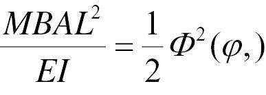
The magnetic tip of the soft continuum robot deflects under a uniform magnetic field, and the length of the soft continuum robot can be expressed as

where E is Young’s modulus, I is the inertia area moment, M is the magnetization density, A is the cross-sectional area, ϕ is the angle of the applied magnetic field, θ is the angle between the tangent of a point and the reference direction, and Φ(ϕ,) is the nondimensional function. Equation (3) can be simplified as

The angular displacement of the free end can be obtained from Equation (4).
The magnetic end, owing to its response to a magnetic field, can be used to measure properties of biological tissues (Figure 1(C)). The magnetic force of the continuum soft robot tip was measured by using a soft rod with a known elastic coefficient and an electromagnet, as shown in Figure 2(A). The magnetic tip was bonded to the soft rod, and both were in the same horizontal plane as the electromagnet. After the distance between the electromagnet and the magnetic tip was fixed, a current was applied to the electromagnet to deform the soft rod. According to the measured deflection of the soft rod, the magnetic force can be calculated as

The Magnetic Force Acting on the Soft Tip.
(A) Magnetic soft tip calibration. (B) Relationship between the current and magnetic force.

where k is the elastic coefficient of the soft rod, and ∆x is the deflection of the soft rod.
Therefore, the magnetic force of the soft continuum robot tip at each current can be calculated according to Equation (5). The relationship between the current and magnetic force is shown in Figure 2(B). The results indicated a linear correlation between the magnetic field strength and magnetic force of the soft continuum robot tip.
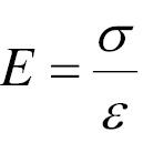
According to the magnetic force of the soft continuum robot tip, the cellular Young’s modulus can be calculated by

where σ=F/A is the stress, F is the force, A is the contact area, ɛ=∆L/L is the strain, ∆L is the deformation, and L is the cell size.
Deflection and Motion of the Soft Continuum Microrobot
The movements of the soft continuum microrobot include deflection and forward motion. To allow the microrobot to make sharp turns, we used a softer silicone to connect the magnetically responsive part and the soft part of the soft continuum microrobot. The softer connection and more responsive magnetic tip enabled large-angle deflection of magnetic tip depending on the direction and strength of the external magnetic field, as shown in Figure 3(A) and Video 1. The magnetic tip achieved a deflection of 270°, thus demonstrating the high flexibility of our soft continuum microrobot.

The Deflection and Motion of the Soft Continuum Microrobot.
(A) Deflection of the magnetic tip under the external magnetic field. (B) The motion of the soft continuum robot.
In contrast to conventional continuum robots, which are pushed to advance by the distal end of the microrobot, our continuum robots were unable to be pushed by the distal end, because of their small size and softness. Therefore, we used Helmholtz coils and a permanent magnet collectively to control the magnetic tip to actuate the soft continuum microrobot advance. An oscillating magnetic generated by Helmholtz coils was used to vibrate the magnetic tip to eliminate the adhesion force between the magnetic tip and the surface. The permanent magnet was responsible for steering and providing traction for forward motion. As shown in Figure 3(B) and Video 2, the magnetic soft continuum microrobot advanced under the combined action of Helmholtz coils and permanent magnets.
Experimental Results
System Setup
As shown in Figure 4, the soft continuum robot system consisted of two parts: a motion control part and vision part. The motion control part comprised a Helmholtz coil system and an electromagnet. A current signal was first generated by a function generator (AFG-2225, GW Instek, China) and was amplified by a power amplifier (ATA-3090, Aigtek, China).
The vision part consisted of a monocular microscope (CX- 10C, Hirox) and a digital camera (DFK 23U274, Imagingsource). The vision part was used to observe and record the experimental process.
Transportation of Zebrafish Cells
To verify the transportation capability of the soft continuum microrobot, we used zebrafish cells (800 μm). Experiments were performed in a water solution. During the entire process, the permanent magnet was used to control the steering of the soft continuum microrobot. Motion of the microrobot was achieved by simultaneous vibration and pulling of the magnetic tip of the microrobot. As shown in Figure 5 and Video 3, the zebrafish cell was transported to the expected position by the magnetic soft continuum microrobot tip. Therefore, the magnetic soft continuum microrobot can manipulate micro-objects.
Mechanical Characterization Measurement
To demonstrate the ability of our proposed soft continuum microrobot to perform mechanical characterization of biological tissue in blood vessels, we used zebrafish cells as manipulation targets. First, the soft continuum microrobot was pulled to approach the zebrafish cell until the magnetic tip nearly contacted the cell, as shown in Figure 6(i). The magnetic tip was subjected to a magnetic field force to squeeze the zebrafish cell when an external magnetic field was applied. Figure 6(ii) shows the deformation of a zebrafish cell during squeezing, as demonstrated in Video 4. The contour obtained with edge detection was used to achieve deformation. In the experiment, the magnetic force of the magnetic tip was 27.5 μN, and the deformation of the zebrafish cell was 125 μm. Thus, Young’s modulus of the zebrafish cell was 1.05 MPa. Our findings validated the ability of the magnetic soft continuum microrobot to be applied in biological tissue detection.
Discussion
This study developed a magnetic soft continuum microrobot for sensing the mechanical properties of biological tissue. The soft continuum microrobot was driven by the response of the magnetic tip to magnetic moment and force. The soft continuum microrobot was successfully applied to transportation of zebrafish cells and measurement of the mechanical properties of zebrafish. Our experimental results validated the measurement mechanism by comparison with zebrafish cell reference data.
Limitations
The major limitations of the proposed soft continuum microrobot include the following: (1) For smaller biological targets (less than 10 μm), the microrobot has lower operational precision, thus potentially limiting the applications in the cardiovascular intervention. (2) Measurement of the mechanical properties of zebrafish cells involves extrusion depth and contact area, which require accurate measurement and analysis of images. This study obtained data through manual measurements, thus potentially limiting the measurement results.
Conclusion
This work introduced a magnetic soft continuum microrobot with the ability to measure the mechanical properties of biological tissue. We demonstrated deflection and motion of the continuum microrobot integrating Helmholtz coils and a permanent magnet. Moreover, we calculated the magnitude of the force on the magnetic tip through a soft rod with a known elasticity coefficient. With its capabilities of manipulating and measuring mechanical properties of biological embryos, this novel microrobot has potential applications in cardiovascular intervention, thus shortening the learning curve and decreasing fluoroscopy exposure. Moreover, owing to its flexibility and force controllability, the magnetic soft continuum microrobot could also be used in myocardial regenerative stem cell therapy.


