The history of gold nanoparticles as tools for biological research and medical diagnostics starts more than a century ago. In 1912, Carl Friedrich August Lange invented a nanoparticle-based test to diagnose “dementia paralytica”. The test was based on colour change upon aggregation induced by non-specific interactions with proteins from the spinal fluids of patients [1]. For several decades, the test was used in clinics and its existence spurred synthetic efforts towards better nanoparticle preparations [2]. With the development of electron microscopy in the 1940s and 1950s, gold nanoparticles became contrast agents of choice due to their high electron density, favourable dimensions and relative ease to prepare antibody conjugates. Some of the earliest studies of vesicular trafficking used gold colloids as electron microscopy probes. In 1957, Harford et al exposed HeLa cells to gold nanoparticles, observed localisation within intracellular vesicles by electron microscopy and concluded that their results supported the notion that “membranous organelles of the cytoplasm may be derived from the cell membrane” [3]. Thus, nanoparticles have been one of the early tools that biologists have used to decipher the way cells probe their environment. They were also used as a proxy to study the entry of biological nanoparticles, i.e. viruses, into cells. As early as 1965, it was noted in an elegant side-by-side electron microscopy study that while the Herpes viral particles escape endosomes, gold colloids remain in vesicles after uptake [4]. Indeed virions, being under a selective reproductive pressure, have evolved advanced means by which to escape their encapsulating vesicle and access the cytosol (for example, adenovirus [5]). Thus, more than five decades of work have clearly established that nanoparticles enter cells by endocytotic mechanisms that result in their entrapment inside intracellular vesicles unless those nanoparticles are biological in nature and have acquired through evolution, advanced molecular tools which enable them to escape. Access to the cytosol remains one of the main barriers towards biologics and siRNA therapeutic application [6–9]. For cell biology experiments, access to the cytosol can be gained through disruptive physical means such as electroporation or endosomal rupture through the use of osmotic pressure [10], liposome carriers or the proton sponge effect. [11] For purposes such as transfection, it is often acceptable that most particles remain trapped in endosomes as long as a few particles per cell reach the cell machinery.
From the first decade of this century, the number of publications reporting the interaction and uptake of nanoparticles in cells has exploded, sometimes ignoring the knowledge gained from these earlier experiments. The idea that nanoparticles have a special capacity to cross biological barriers became pervasive, leading to concerns regarding their toxicity and hopes regarding their potential for therapeutic applications. Yet, both the concerns and the hopes appear to rest on limited data. The claim that nanoparticles can cross the cell membrane and access the cytosol seems to have entered the scientific literature through a 2005 article and a high-profile review published in 2006 by Geiser et al [12], and by Nel et al [13] respectively. The claim was challenged the following year by Shayla Banerji and Mark Hayes in an elegant experimental and theoretical study which was a direct response to the two papers cited above [14]. Unfortunately the refutation had a limited impact on the field. Thus, nanoparticles were proposed for intracellular sensing within the cytosol of live cells (without direct evidence of endosomal escape) including the detection of caspase three activity by plasmon rulers [15] and the regulation, quantification and imaging of specific mRNAs with spherical nucleic acids [16]. In both cases, the interpretation of the experiments relies on the particles being in the correct compartment: retention of the majority of the particles in endosomes would lead to incorrect conclusions.
RNA plays a central role in the conversion of DNA into proteins in cells. More than just a genetic translator, these highly specialised molecules play an active and highly dynamic role in gene expression, promoting silencing, up-regulation or modification of translation. Present studies on RNA are largely restricted to fixed or in vitro methods such as Fluorescent in situ Hybridisation (FISH), RT-PCR and gel electrophoresis. Fluorescent reporters that could get live, dynamic measurements of mRNA within cells or tissues would therefore have an enormous potential to improve our understanding of biology. The spherical nucleic acids gold nanoparticles developed by the Mirkin lab for detection of mRNA, are commercially available from EMD Merck Millipore under the name SmartFlares. The technology relies on the hybridisation of target mRNA strands with complementary strands which are covalently linked to a gold nanoparticle. Upon hybridisation a fluorescent reporter strand is displaced, and subsequently unquenched when no longer in the vicinity of the gold core, providing a readout of mRNA levels. A more recent implementation (named StickyFlares) relies on the same technology but inverts the sequences such that the fluorescent reporter strand is complementary to the mRNA of interest [17].
Given the limited amount of published information on the endosomal escape of spherical nucleic acids, we have studied the localisation of their commercially available form, i.e. SmartFlares. We have carried this research as an open science project, sharing our data and protocols in quasi-real time using an online notebook [18] and data repository [19]. This has allowed us to gather feedback from peers including other SmartFlare users and developers. Using high-resolution fluorescence microscopy, electron microscopy and photothermal imaging we have found that using the manufacturers’ instructions, the SmartFlares are taken up into vesicular compartments in a subset of cells. We find that after 16–20 hours, fluorescence is present and remains visible as puncta within membrane-contained vesicles. Importantly, the fluorescence levels are independent of the presence of the target mRNA. Given these findings, we suggest that the validation of any nanoparticle-based probes for intracellular sensing should include a quantitative and thorough demonstration that the probes can reach the cytosolic compartment.
MATERIALS & METHODS
Materials
SmartFlare mRNA detection probes were ordered from EMD Merck Millipore. Uptake and Scrambled controls were Cy5-labelled while VEGF SmartFlares were Cy3-labelled. SmartFlares were re-suspended in 1 mL nuclease free de-ionised water and stored at room temperature protected from light according to the manufacturer’s instructions.
Fluorescein isothiocyanate (FITC)-labelled 10 kDa dextran (from Life Technologies - now ThermoFisher Scientific) was re-suspended to 10 mg/mL in phosphate-buffered saline (PBS). Dimethyloxaloylglycine (DMOG), Triton X-100 and Bovine Serum Albumin (BSA) were from Sigma Aldrich. DMOG stocks were used within 2 months of reconstitution and aliquoting into −20°C. All cell culture media was from Gibco (now ThermoFisher Scientific).
Primary antibodies were ordered from Abcam against LAMP1 (AB24170) and Transferrin Receptor (AB84036). Secondary antibodies were ordered from Life Technologies (now ThermoFisher Scientific) conjugated with AlexaFluor 488 (A11008), 568 (A11011) or 647 (A21244) as required.
HeLa cells (ATCC) were grown in 10 cm dishes (Corning) and split into 35 mm glass-bottomed dishes (Ibidi) for experiments.
Cell culture
HeLa cells were maintained in Dubecco’s Modified Essential Medium (DMEM) growth media supplemented with 10% Fetal Bovine Serum (FBS), 1% non-essential amino acids and 1% penicillin/streptomycin. Cells were maintained between 20 and 80% confluent at 37°C and 5% CO2.
SmartFlare mRNA detection experiments
The SmartFlare RNA detection probes were used as directed by the manufacturer. Briefly; ~4×10[5] HeLa cells were seeded onto 35mm diameter glass-bottomed imaging dishes and incubated in growth media for 6 hours to adhere. Media were pre-mixed by aliquoting (per well) 960 μL of media, 20 μL of SmartFlare stock solution, 20 μL of fluorescent dextran (10 mg/mL stock). In experiments with DMOG, the drug was included at 500 nM and the volume of media reduced accordingly to compensate. Growth media was replaced with the above mixture and the cells returned to the incubator for 18h or as noted.
Quantitation of mRNA using qPCR
Approximately 1×10[8] cells were seeded into 6 cm diameter dishes, allowed to adhere for 6 hours then treated with or without 500 nM DMOG for 18 hours to replicate the SmartFlare experiments. Quantitative PCR was then performed as previously described [20]. Primers used were;
Confocal microscopy
Fluorescent imaging was conducted at the Centre for Cell Imaging (CCI) in Liverpool using a Zeiss LSM510 multiphoton microscope. Where possible, multi-pass dichroic mirrors and filters were used to reduce the potential for spatial misalignment. In all experiments, the confocal pinhole was adjusted to maintain a similar optical section between channels. For live experiments, incubation and CO2 control maintained environmental conditions as in ‘Cell Culture’ above. Unless otherwise stated, all fluorescent images are shown without any contrast enhancement.
Electron microscopy
Cells were fixed with a solution containing 1% paraformaldehyde and 3% gluteraldehyde in 0.1 M cacodylate buffer (pH 7.4). They were stained first with reduced osmium (2% OsO4 + 1.5% K4[Fe(CN)6]). This was followed by a second osmium staining (2% OsO4) and a uranyl acetate (1%) staining. Samples were then dehydrated in graded ethanol (30%, 50%, 70%, 90% and twice 100%). Finally, samples were infiltrated with medium TAAB resin 812 and embedded with the same resin. The resin was cured for 48 h at 60°C.Ultrathin sections of 350 μm × 350 μm × 74 nm were cut and placed in 200 mesh formvar/carbon filmed grids. They were post-stained with uranyl acetate and lead citrate before imaging on a Tecnai G3 spirit.
Photothermal Microscopy
Cells were fixed in 4% PFA for 20 min at room temperature. Subsequently, the cells were washed with PBS and immersed under 2 mL of PBS + 0.01% sodium azide for storage at 4°C between imaging sessions.
All images were acquired using a custom photothermal microscope [21] built around the body of a Nikon Eclipse Ti-U inverted microscope. Prior to photothermal imaging, the samples were allowed to equilibrate fully to room temperature for at least an hour. Fluorescence images were recorded using an X-Cite Series 120 light source (now Excelitas Technologies, USA) together with a FITC filter set for the Dextran signal and Cy5 filter set for the SmartFlare signal immediately prior to photothermal imaging.
The photothermal excitation laser (523 nm, frequency-doubled Nd:YAG, Ventus Laser Quantum, Germany) was tuned to 0.5 mW and modulated at a frequency of 459.5 kHz using an accousto-optical modulator (Isomet Corporation, UK). The excitation beam was overlaid with a 1.0 mW non-resonant probe laser (633 nm, JDS Uniphase Corporation, USA) via a cold mirror (ThorLabs, USA). The superimposed beams were focused onto the sample via a Zeiss Plan Achromat 63× oil immersion objective (numerical aperture: 1.4). The sample was placed on a piezo scanning stage (MCL502385, MadCity Labs, USA), which allows the movement of the sample in three dimensions over the fixed laser spot. Pixel-by-pixel scanning was facilitated by a piezoelectric stage driver (MCL NanoDrive 85, MadCity Labs, USA) controlled through a Nanonis RC4 module and Nanonis program (SPECS Zurich, Switzerland). The transmitted and forward scattered light was collected via a Zeiss Achroplan 40× water immersion objective (numerical aperture: 0.8) and passed through a red-pass filter (ThorLabs, USA) to block the excitation laser. The red component was focused on a photodiode of the balanced photo receiver (Model 2107 10 MHz adjustable photo receiver, New Focus, USA). A lock-in amplifier (DSP 7260, Signal Recovery, USA) was used to identify the scattered component of the probe beam that corresponds to the modulation frequency (i.e. 459.5 kHz). A Nanonis SC4 Acquisition Module (SPECS Zurich, Switzerland) was used for signal acquisition. The signal was averaged and a grayscale pixel value was generated. The pixel-by-pixel values were then converted into a photothermal image and saved in the Nanonis-native .sxm format.
Immunofluorescence
Cells were treated identically as to the “mRNA detection experiments” above, however instead of imaging the samples live, they were washed once in Phosphate Buffered Saline (PBS), then fixed in 4% PFA for 20 min at room temperature. Subsequently, samples were washed at least once with PBS to remove excess fixative then blocked and permeabilised using 0.1% TritonX-100 plus 1% Bovine Serum Albumin (BSA) in PBS for 60 minutes at room temperature. Samples were washing three times with PBS. Primary antibodies were diluted in 1% BSA in PBS at 1:500, and added to the samples for 60 mins at room temperature. Samples were washed three times for 15 mins each in PBS, then secondary antibodies were added at 1:1000 dilution in 1% BSA in PBS for 60 mins at room temperature. Cells were washed three times in PBS then imaged immediately or stored under 2 mL of PBS + 0.01% sodium azide at 4°C for later imaging.
Data analysis
All data analysis was performed using Fiji (available from http://fiji.sc). In Figure 1, estimates of particle size were made on calibrated images by thresholding the electron dense particles by intensity, followed by the application of a 2D watershed filter to split separating objects. The Analyze Particles function was used to report the minimum and maximum Feret diameters of particles with an area greater than 100 nm[2] with circularity greater than 0.7 (to exclude amorphous bunches of particles). For each particle, the mean of the maximum and minimum Feret diameter were calculated. The population mean is reported.

In Figure 3, the change in intensity after DMOG treatment was measured by background subtracted raw integrated density for a field of cells and dividing this by the number of cells in the field. Within experimental repeats, the data were normalised to an untreated control, and the mean of these values were reported. The results of three experiments (each with 8 fields) were analysed in this way. A two-tailed heteroscedastic Student’s t-test was used to assess significance (P = 0.065).

In Figure 4, the SmartFlare fluorescence channel was compared to a second channel (see Figure for details) and analysed using the JaCoP plugin for Fiji, [22] for colocalisation using a thresholded Manders’ analysis. Reported (yellow number) is the mean of 12 fields (approximately 20 cells per field) from two independent experiments (TFN-R & LAMP1) or 24 fields from two separate experiments (dextran). Given the non-homogeneous uptake of SmartFlares by cells, the values reported are the coefficient relating to the overlap between SmartFlares and the secondary label.

Open science
This project has been run as an Open Science project, with results, thoughts, commentary and discussion posted at [http://raphazlabcommons.wordpress.com]. The raw data were both managed internally and made available, through the OMERO server at the Liverpool Centre for Cell Imaging (CCI). We would like to acknowledge the help of the Open Microscopy Environment group (University of Dundee), specifically Will Moore, for help with developing our public-facing gallery hosted at [http://cci02.liv.ac.uk/gallery].
RESULTS AND DISCUSSION
Characterisation of SmartFlare RNA detection probes
As an exemplar target, we chose the Vascular Endothelial Growth Factor (VEGF) because it is present in all mammalian cells, its regulation is relevant to a range of diseases, and its expression level can be manipulated pharmacologically with dimethyloxalylglycine (DMOG). [23, 24]
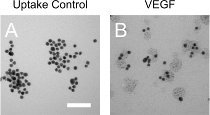
As gold nanoparticles have a known propensity to aggregate and agglomerate, we sought to first characterise the VEGF SmartFlares along with the ‘Uptake Control’. Transmission electron microscopy (TEM) showed no apparent aggregation (Figure 1 A & B) of the particles and allowed a measurement of the particle diameters (VEGF: 16 nm, SD = 2.34 nm, n = 310 particles; uptake control: 14 nm, SD = 1.82 nm, n = 93 particles) which compared well to the expected diameter of 13 nm.
SmartFlares are taken up into cells
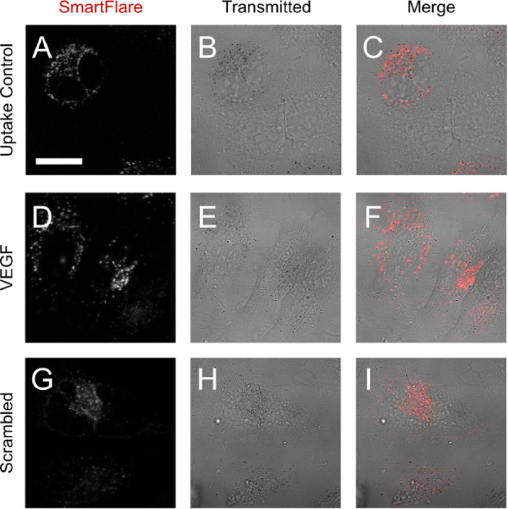
Following the manufacturers’ instructions, Uptake Control SmartFlares were added to HeLa cells and incubated for 18 hours. Live-cell imaging with a laser-scanning confocal microscope revealed fluorescent puncta of ~1 μm diameter (Figure 2A and the project’s online data repository at [http://cci02.liv.ac.uk/gallery]). Surprisingly, not all cells appeared to internalise the Uptake Control SmartFlares, as evidenced by a lack of detectable fluorescent signal in some cells (Figure 2C). Both the VEGF and Scrambled SmartFlares showed a very similar punctate distribution within the cells. This was unexpected for two main reasons. Firstly, SmartFlares are sold on the basis of being able to escape the endosomes in order to interact with RNA in the cytosol [25, 26]. Secondly, in order to become fluorescent, the SmartFlares are ostensibly required to interact with target RNA molecules, of which we would expect limited amounts within newly formed endocytic vesicles.

SmartFlares remain in vesicles up to 18 h
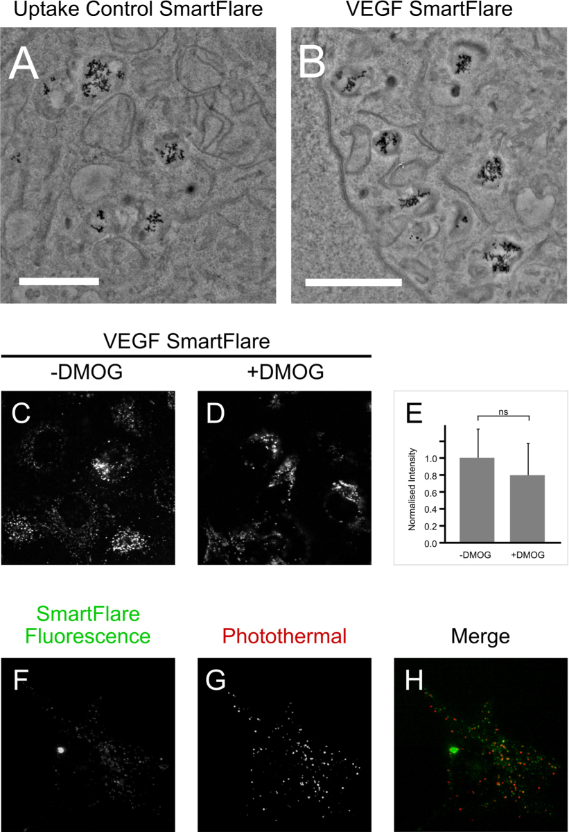
The punctate distribution seen in Figure 2 could result from aggregation in the cytosol, vesicular containment or binding to the surface of cells. In order to examine this at higher resolution, SmartFlare-loaded cells were imaged using transmission electron microscopy (TEM). From an initial screen of the EM grid studying at least 20 cells, gold particles were only seen to be contained within membrane-bound compartments (Figure 3A-B). Some sections did not present any gold nanoparticles.
The TEM data show that the SmartFlares are contained within membrane-bound compartments. To test whether their fluorescence is nevertheless sensitive to the levels of VEGF mRNA, cells were treated with 500 nM DMOG at the time of SmartFlare addition. Previous studies have shown DMOG to increase VEGF mRNA levels by 10 fold in different cell types. [27] Here, DMOG increased VEGF mRNA on average 19 fold (21, 15 and 22 fold in three independent experiments). As shown in Figure 3C-E however, 18 hours of DMOG treatment did not affect the intensity of the VEGF SmartFlare signal.
To evaluate the respective localisation of the gold core and unquenched fluorescence reporter, we combined fluorescence and photothermal microscopy to visualise the gold core and fluorescent dye in the same sample. This showed the fluorescent puncta and nanoparticles to be within the same compartments (Figure 3F-H).
Characterisation of the SmartFlare-containing vesicles
Having confirmed that the SmartFlares were membrane-bound, we set about trying to characterise the SmartFlare-containing compartments. There are several ways in which material impermeant to the cell membrane can be taken up into cells. Endocytosis is probably the most well studied category and is largely driven by receptor-mediated signalling, whereas pinocytic processes are considered constitutive and are responsible for fluid-phase (IE receptor independent) uptake. The terminal compartment of these processes is the lysosome, a highly nucleolytic and proteolytic compartment involved in degradation and in some cells, antigen presentation.
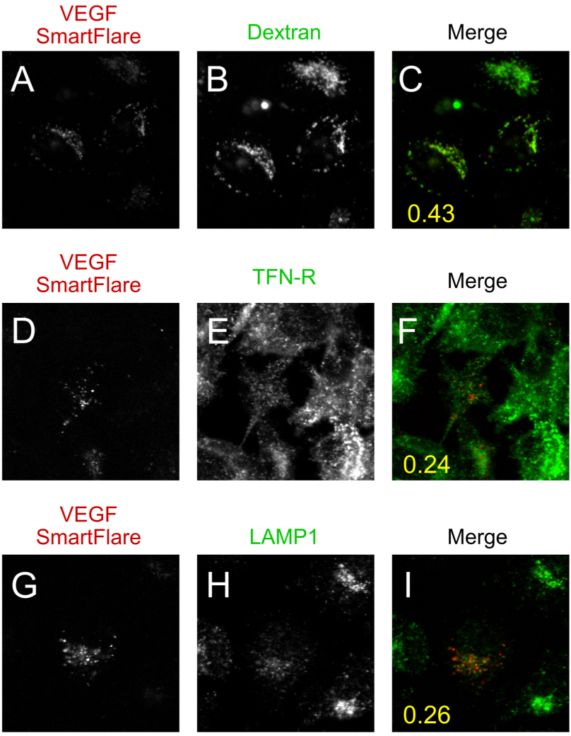
We labelled the endocytic pathway using a fluorescently-labelled 10 kDa dextran, both to show that constitutive uptake was occurring in our system, but also to label all of the compartments of the pathway. As expected, the dextran labelled every cell in the field with homogeneous intensity puncta (Figure 4B). There were approximately the same number of vesicles per cell when corrected for cell size. Interestingly, the dextran and SmartFlares showed a Manders’ colocalisation coefficient of 0.43 (Figure 4C: see Methods for details). Furthermore, much the same was seen at a 2 hour time point (Supplementary Figure 1).
As the dextran may be excluded from receptor-mediated endosomes (by unknown mechanisms) we also used immunofluorescence to label the recycling (transferrin-receptor positive) and terminal (lysosomal) compartments of the endocytic pathway (Figure 4D-F and G-I respectively). Upon analysis, the SmartFlares showed little overlap with either of these compartments (Figure 4C,F,I, mean Manders’ coefficient of at least 12 fields from two independent experiments is inset), suggesting a parallel but largely non-overlapping compartment.
CONCLUSIONS
Developing the Green Fluorescent Protein (GFP) into a tool for researchers was a landmark achievement across many fields and has opened up the dynamic study of proteins in living cells [28]. There is no doubt that replicating this success in the study of RNA would be equally as momentous. Our results however, indicate that SNAs in their present incarnation, cannot be used to report on mRNA levels in live cells. Furthermore, we have shown that SNAs are taken up into only a subset of cells (which could potentially bias population studies). Once taken up we consistently observe a punctate distribution indicating retention within vesicular compartments. This was confirmed by electron microscopy and photothermal imaging. Furthermore, the controls (the scrambled and constitutively-fluorescent uptake control) showed similar levels of fluorescence. As the fluorophore should only be unquenched in the presence of cognate mRNA, which we assume is not present in the vesicles, this signal is likely the result of a nucleolytic cleavage of the oligonucleotide strands. Indeed the Mirkin group themselves have published a comprehensive study on the vesicular retention, localisation and degradation of SNAs, particularly highlighting the role of DNaseII [29].
The same study highlights what an effective tool this must be if only a “…small, unquantifiable portion of these particles escape the endosome…” (ibid). Even if we accept the possibility of a small fraction of these particles being released, unscathed into the cytosol, we still have the issue of overcoming background signal. StickyFlares (and presumably by extension, SmartFlares) are reported to increase in fluorescence intensity ten times upon un-quenching [17], which means that even if as many as one in eleven are released, the signal would not be visible over the background fluorescence. All of this is ignoring cleavage and unquenching inside of the vesicle, which would further increase the background.
These findings leave us with the difficult job of interpreting the existing body of work published using these probes. It is likely that publication bias is playing a role: we do not know how many laboratories have bought and tried the SmartFlare reagents versus how many have published their results. Most of the published SmartFlare data are cytometry results which do not give any indication of the cellular localisation of the signal. Interestingly, when imaging data are included they show a punctate distribution in cells [30–32] although this is not commented upon. There have been other cases, most notably that of antisense technology, working but having an effect through means other than traditional Watson-Crick base pairing [33]. Thus, in addition to confirmation bias, some of the published work may result from poorly understood off-target effects.


